

⚠️ The 10th Gen CAN Bus Complexity
This is a key 10th gen specific electrical consideration that is not covered in standard wiring references.
The 10th gen Civic features extensive CAN bus integration compared to previous generations. All major modules communicate over the F-CAN network — the BCM/MICU, PCM, gauge cluster, camera unit, and TCM are all on the same data bus. If one module is disconnected, the others may throw codes and experience functionality issues.
Scenario: During a CVT-to-manual transmission swap, the TCM is disconnected. The vehicle may not start, the gauges may become inoperative, and the camera unit may throw codes. This occurs because the BCM, gauge cluster, and camera unit expect TCM data packets on the F-CAN bus.
Fix: Either keep the TCM connected (even if the CVT has been removed) to maintain CAN bus communication, or have the BCM and gauge cluster reflashed for a manual transmission configuration. Removing modules without addressing the CAN bus architecture is not recommended.
10th Generation — Civic (2016–2021) FC1/FC2/FC3/FC4/FK7/FK8
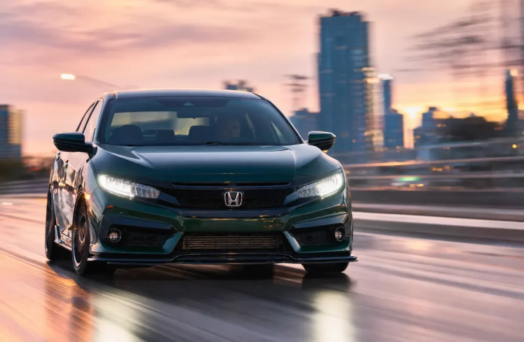
Your 10th gen Civic (FC1 sedan, FC2 coupe, FC3/FC4 sedan variants, FK7 hatchback, FK8 Type R) features a significantly different wiring architecture from the 8th and 9th gens. The system is built around CAN bus networks — F-CAN for powertrain and B-CAN for body functions. Chassis codes include FC1, FC2, FC3, FC4, FK7, and FK8. All engines are turbocharged — L15B7 (1.5T) and K20C1 (2.0T Type R).
Here is the breakdown of each wire you will need — including the 10th gen specific CAN bus considerations that are not covered in generic wiring references.
Wire Color Legend — 10th Gen Specific
The 10th gen uses Honda’s standard color codes with additional CAN bus wiring. Wire colors may vary between standard and premium amplified systems.
| Code | Color | Common Function (10th Gen) |
|---|---|---|
| BLK | Black | Ground — always ground |
| BRN | Brown | Constant 12V battery power — Pin 3 in the 24-pin plug |
| RED | Red | Switched 12V (ACC/IGN) — Pin 23 in the 24-pin plug |
| LT GRN | Light Green | Front left speaker (+) |
| LT BLU | Light Blue | Front left speaker (-) |
| GRY | Gray | Front right tweeter (+) |
| PUR | Purple | Front right tweeter (-) / Front right woofer (+) |
Stereo Wiring — 10th Gen (2016–2021)
The 10th gen offers multiple radio configurations that vary by trim:
- Base models: Standard radio with 24-pin main connector
- Premium Audio (Touring / Sport Plus): 11-speaker system with external amplifier
- Display Audio: 7-inch or 9-inch touchscreen with integrated amplifier
| Function | Wire Color | Pin Location |
|---|---|---|
| Battery (+12V Constant) | BRN | Pin 3 in 24-pin plug |
| Accessory (12V Switched) | RED | Pin 23 in 24-pin plug |
| Ground | BLK | Pin 1 in 24-pin plug |
| Front Left Speaker (+) | LT GRN | Pin 15 in 24-pin plug |
| Front Left Speaker (-) | LT BLU | Pin 16 in 24-pin plug |
| Front Right Speaker (+) | GRY | Pin 17 in 24-pin plug |
| Front Right Speaker (-) | PUR | Pin 18 in 24-pin plug |
| Rear Left Speaker (+) | BLU | Pin 5 in 24-pin plug |
| Rear Left Speaker (-) | WHT | Pin 6 in 24-pin plug |
| Rear Right Speaker (+) | YEL | Pin 7 in 24-pin plug |
| Rear Right Speaker (-) | BRN | Pin 8 in 24-pin plug |
💡 Premium Sound — Amplifier Location
For vehicles equipped with the premium 11-speaker system (Touring, Sport Plus, or Si with subwoofer), an amplifier is located under the passenger seat. The speaker wiring from the amplifier differs from the base model configuration.
From a UK 2019 Sport Plus with premium audio:
- Front Left Woofer (+): Position A5 — LT GRN
- Front Left Woofer (-): Position A6 — LT BLU
- Front Right Woofer (+): Position A12 — PUR
- Front Right Woofer (-): Position A13 — GRY
- Front Left Tweeter (+): Position A14 — YEL
- Front Left Tweeter (-): Position A15 — GRN
- Front Right Tweeter (+): Position A16 — LT GRN
- Front Right Tweeter (-): Position A17 — PNK
Note: Subwoofer outputs may be unpopulated in some market configurations (e.g., UK models may not include the subwoofer).
ECU Pinout — L15B7 (1.5T)
The L15B7 ECU is located behind the glove box — consistent with the 8th and 9th gens. ECU part numbers begin with 37820-5AA-Axx or similar. Full factory wiring diagrams are available for the FC/FK chassis through Honda service information.
Common 10th Gen ECU Part Numbers:
| Engine | ECU Part Number | Notes |
|---|---|---|
| L15B7 (1.5T — Base / EX / Sport) | 37820-5AA-Axx | 1.5L SOHC i-VTEC Turbo — 6MT or CVT |
| L15BY (1.5T — Some markets) | Varies | 1.5L SOHC i-VTEC Turbo |
| L15BA (1.5T — Some markets) | Varies | 1.5L SOHC i-VTEC Turbo |
| K20C1 (2.0T — Type R FK8) | 37820-5BF-Axx | 2.0L DOHC i-VTEC Turbo — 6MT only |
Critical Ground Locations — 10th Gen
The 10th gen uses a ground layout similar to previous generations, with additional ground points for modern electronic modules.
| Ground Code | Location | What It Grounds |
|---|---|---|
| G101 | Top left side of engine block | ECU reference ground, engine sensors |
| G201 | Behind right side of front bumper | Headlights, cooling fans, body electronics |
| G401 | Transmission housing area | A/C condenser fan motor, starter return, hood latch switch |
| G501 | Under dash, driver side | Interior electronics, stereo, dash |
CAN Bus Architecture — Key Considerations
The 10th gen Civic features two CAN bus networks:
- F-CAN (Powertrain CAN): Connects the PCM, TCM (CVT), VSA/ABS, gauge cluster, and multipurpose camera unit
- B-CAN (Body CAN): Connects the BCM/MICU, door modules, and body electronics
⚠️ CAN Bus Module Interdependence
On the 10th gen, all modules on the F-CAN network expect data from every other module. If a module is disconnected (e.g., removing the TCM during a CVT-to-manual swap), other modules may throw codes and may not function correctly.
Symptom: After a CVT-to-manual transmission swap, the gauge cluster may not function, the camera unit may throw U0101, and the vehicle may not start.
Solutions:
- Option 1: Keep the TCM connected to maintain F-CAN bus communication (even if the CVT has been removed). Connect the TCM’s F-CAN lines, +B power, and ground.
- Option 2: Replace the BCM/MICU, gauge cluster, and camera unit with manual-spec units. This requires dealer immobilizer registration.
- Option 3: Develop a CAN packet emulator to transmit the missing TCM data on the bus. This requires sniffing the required packets from the original TCM.
Important Notes — 10th Gen Specific Wiring Issues
💡 BCM Parasitic Battery Drain — 2016-2019 Models
Some 10th gen Civics, particularly 2017 models, may experience the BCM (Body Control Module) failing to fully power down after the vehicle is turned off. This results in a parasitic current draw that can drain the 12V battery over time.
Symptom: The battery is drained overnight or over several days. Multiple battery replacements have not resolved the issue.
Fix: The BCM itself is the root cause — it remains partially active and drains the battery. This is a documented issue on 10th gen Civics. Repair costs typically range from $150 to $900.
🔧 Aftermarket Radio Install — CAN Interface Required
For aftermarket head unit installations on a 10th gen, a CAN bus interface box (such as the unit included with some aftermarket head units) is required to retain steering wheel controls and factory functions.
Common issue: No audio after installation. The solution is to connect the RCA jacks to the CAN bus interface box plugs — the included instructions are often unclear. The CAN interface handles amplifier and speaker output integration.
💡 Flex Fuel / CAN-Based Tuning
For aftermarket tuning on the L15B7 or K20C1 with flex fuel (E85), a CAN-based flex fuel kit such as the Hondata CANFlex is commonly used.
These kits interface with the CAN bus network to transmit ethanol content data to the ECU. Supported on 10th gen Civic 1.5T (2016-2021) and Type R. This provides a clean installation without the need to splice into analog sensor wires.
💡 Factory Wiring Diagrams Are Available
Full factory wiring diagrams for the 10th gen (FC/FK chassis, 2016-2021) are available through Honda’s official service information portal. The documentation covers the L15BY, L15BA, L15B7, and K20C1 engines, with both 6MT and CVT transmissions.
Pinouts for amplifier connectors, speaker wiring, and CAN bus circuits are also available through Honda service information portals.
❓ 10th Gen Civic Wiring — Frequently Asked Questions
1. Where is the ECU located on a 10th gen Civic?
The ECU is located behind the glove box on the passenger side — consistent with the 8th and 9th gens. Remove the glove box for access.
2. What ECU does a 10th gen Civic 1.5T use?
The 2016-2021 Civic 1.5T (L15B7) uses ECU 37820-5AA-Axx. The Type R (K20C1) uses ECU 37820-5BF-Axx.
3. What are the stereo wire colors on a 10th gen Civic?
Battery: BRN (Pin 3), ACC: RED (Pin 23), Ground: BLK (Pin 1). Front left: LT GRN (+) / LT BLU (-). Front right: GRY (+) / PUR (-). Rear left: BLU (+) / WHT (-). Rear right: YEL (+) / BRN (-).
4. Where is the amplifier on a 10th gen Civic with premium audio?
The amplifier is located under the passenger seat on premium audio models (Touring, Sport Plus, Si with subwoofer).
5. What are the ground locations on a 10th gen Civic?
Key grounds: G101 (engine block), G201 (under right bumper), G401 (transmission), G501 (under dash). G401 also grounds the A/C Condenser fan motor.
6. What is the F-CAN network on a 10th gen Civic?
The F-CAN (Powertrain CAN) connects the PCM, TCM, VSA/ABS, gauge cluster, and camera unit. All modules on this network expect data from each other — disconnecting one may cause codes in others.
7. Why does my 10th gen Civic battery keep dying?
On 2016-2019 models, particularly 2017, the BCM may fail to fully power down and cause parasitic Battery Drain. The BCM remains partially active and can drain the battery over time.
8. Can I do a CVT-to-manual swap on a 10th gen Civic?
Yes, but it requires addressing CAN bus integration. The TCM (CVT computer) must remain on the F-CAN network, or the BCM, gauge cluster, and camera unit will throw codes. Options include keeping the TCM connected, replacing affected modules, or developing a CAN packet emulator.
9. Where can I find wiring diagrams for my 10th gen Civic?
Full factory wiring diagrams are available through Honda’s official service information portal for the FC/FK chassis (2016-2021). The documentation covers all engines (L15BY, L15BA, L15B7, K20C1) and transmissions (6MT, CVT).
10. Do I need a CAN interface for an aftermarket stereo on a 10th gen Civic?
Yes. A CAN bus interface box is required to retain steering wheel controls, factory amplifier integration, and other functions. The CAN interface manages communication between the head unit and the vehicle’s electronic systems.
💡 Pro Tip: The 10th gen Civic is a CAN bus-dependent vehicle — removing modules without addressing the network architecture will cause issues. The BCM, TCM, PCM, gauge cluster, and camera unit communicate over F-CAN. Before modifying wiring, understand each module’s role and the CAN bus routing. Use soldered connections with heat shrink — the CAN bus is sensitive to high-resistance connections, and Scotch-lok connectors are not recommended.
Sources: Honda factory service manual (2016–2021), FC/FK workshop documentation, and verified against real-world owner experience from 10th Gen Civic forums. Wire colors and pin assignments may vary by trim, market, and optional equipment. Always verify with a multimeter before cutting or splicing wires.